SSAO using Visibility Bitmasks
We recently released the paper Screen Space Indirect Lighting with Visibility Bitmask, a rendering technique based on GTAO that replaces the two horizon angles by a bit field representing the binary state (occluded / un-occluded) of N sectors uniformly distributed around the hemisphere slice. It allows light to pass behind surfaces of constant thickness while keeping the efficiency of horizon-based methods.
In this post, we share some code to make it easier to implement in 3D applications and clarify some details from the paper. We take the Unity GTAO code from HDRP as a starting point, to show that our method can be integrated into an existing implementation with only a few modifications.
Like GTAO, the algorithm takes a number of samples in screen space in a number of random directions per pixel. Here is an AO render from the main camera, where each colored dot represents a sample for a single pixel for one given sampling direction:
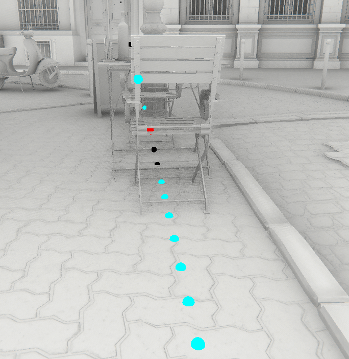
When samples are colored cyan, this means that they don’t contribute to the lighting, either because they are outside the hemisphere, or because a previous sample has already occluded the sector where it could have contributed. Astute readers will notice that most samples don’t contribute to the final image.
Here is a view of the scene from another angle, that shows how a 2D hemispherical slice is positioned in 3D space relative to the view direction and sampling direction:
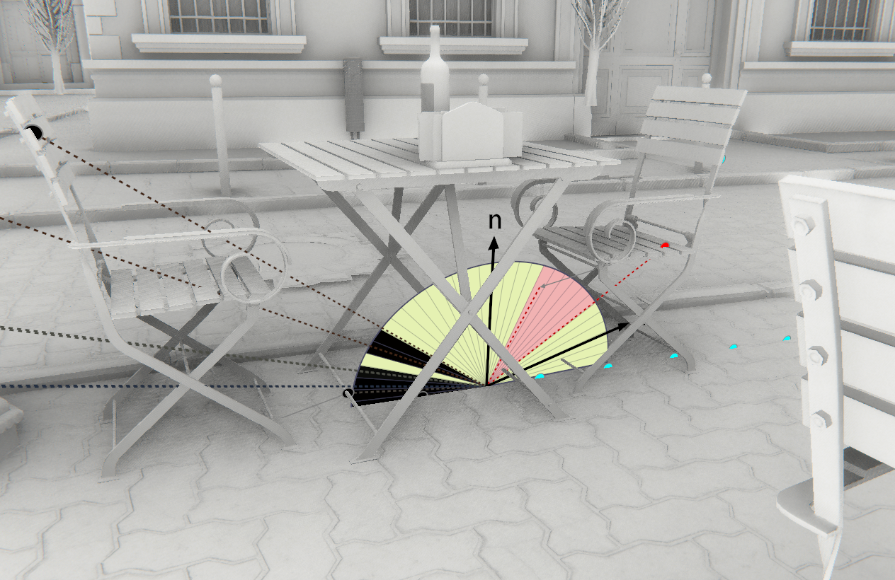
Red sectors mean that the sample could only contribute occlusion (not lighting) to the pixel because it’s normal was not facing the pixel’s normal. When they are black or any other color, this is because they can contribute occlusion and lighting, and the sector’s color is the same as the light’s color. In this example it doesn’t matter because we focus on ambient occlusion, so only occlusion is taken into account.
The following figure shows how multiple slices are placed around the view vector. Slices are always aligned to the view vector V, and have a random orientation in screen space. This means that the projected normal is never the same from slice to slice. Notice that slices are not rotated around the pixel normal but around the view vector:
This is the main loop of the original GTAO code from Unity:
float integral = 0;
float3 V = normalize(-positionVS);

for (int i = 0; i < dirCount; ++i)
{
    float2 dir = GetDirection(dispatchThreadId.xy, i);
    float3 normalVS = GetNormalVS(normalBufferData);
    float3 sliceN = normalize(cross(float3(dir.xy, 0.0f), V.xyz));
    float3 projN = normalVS - sliceN * dot(normalVS, sliceN);
    float projNLen = length(projN);
    float cosN = dot(projN / projNLen, V);

    float3 T = cross(V, sliceN);
    float N = -sign(dot(projN, T)) * GTAOFastAcos(cosN);

    // Find horizons
    float2 maxHorizons;
    maxHorizons.x = HorizonLoop(positionVS, V, rayStart, dir, offset, step, 0);
    maxHorizons.y = HorizonLoop(positionVS, V, rayStart, negDir, offset, step, 0);

    // Now we find the actual horizon angles
    maxHorizons.x = -GTAOFastAcos(maxHorizons.x);
    maxHorizons.y = GTAOFastAcos(maxHorizons.y);
    maxHorizons.x = N + max(maxHorizons.x - N, -HALF_PI);
    maxHorizons.y = N + min(maxHorizons.y - N, HALF_PI);
    integral += AnyIsNaN(maxHorizons) ? 1 : IntegrateArcCosWeighted(maxHorizons.x, maxHorizons.y, N, cosN);
}

integral /= dirCount;
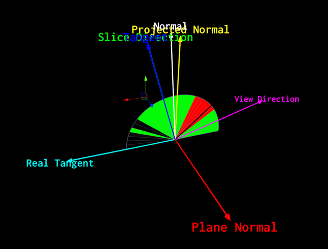
The code starts by looping over dirCount sampling directions. For a given direction i, all the variables required for the slice parametrization are defined. Here is a breakdown of the most important variables:
- V: The view direction (direction from current pixel to camera)
- normalVS: The view-space normal at the current pixel
- sliceN: Unit vector that is perpendicular to the slice plane
- projN: The normal projected onto the slice plane (the normal is almost never aligned with the slice plane)
- T: The slice tangent (perpendicular to V and sliceN)
- N: The angle in radians from V to projN
This is a 3D view of the slice, color-coded with the corresponding variable names above:
Back to the code, the HorizonLoop() function finds the maximum elevation maxHorizon.x for the right part of the hemisphere and maxHorizon.y for the left part.
With those maximum elevations, the algorithm then clamps the horizons to the hemisphere centered on the projected normal, and then computes the integral of the un-occluded regions on each side of the view vector using the IntegrateArcCosWeighted() function.
To use the visibility bitmask approach, we slightly modify the HorizonLoop() function to pass an inout uint globalOccludedBitfield that will be marked with occluded sectors:
// Find horizons
float2 maxHorizons;
uint globalOccludedBitfield = 0;
maxHorizons.x = HorizonLoop(positionVS, V, rayStart, dir, offset, step, 0, globalOccludedBitfield, 1, N);
maxHorizons.y = HorizonLoop(positionVS, V, rayStart, negDir, offset, step, 0, globalOccludedBitfield, -1, N);

#ifdef VISIBILITY_BITMASK
    integral += 1.0 - float(countbits(globalOccludedBitfield)) / float(SECTOR_COUNT);
#else
    // Now we find the actual horizon angles
    ...
#endif
We can then compute the integral by counting the number of occluded sectors and dividing by the total amount of sectors. Note that we do not take the cosine weight into account in this case.
Most of the work happens in the HorizonLoop() function. Here is the original one from GTAO:
float HorizonLoop(float3 positionVS, float3 V, float2 rayStart, float2 rayDir, float rayOffset, float rayStep, int mipModifier)
{
    float maxHorizon = -1.0f;  // cos(pi)
    float t = rayOffset * rayStep + rayStep;

    const uint startWithLowerRes = min(max(0, _AOStepCount / 2 - 2), 3);
    for (uint i = 0; i < _AOStepCount; i++)
    {
        float2 samplePos = max(2, min(rayStart + t * rayDir, _AOBufferSize.xy - 2));

        // Find horizons at these steps:
        float sampleDepth = GetDepthSample(samplePos, i > startWithLowerRes);
        float3 samplePosVS = GetPositionVS(samplePos.xy, sampleDepth);

        float3 deltaPos = samplePosVS - positionVS;

        float deltaLenSq = dot(deltaPos, deltaPos);
        float currHorizon = dot(deltaPos, V) * rsqrt(deltaLenSq);
        maxHorizon = UpdateHorizon(maxHorizon, currHorizon, deltaLenSq);

        t += rayStep;
    }

    return maxHorizon;
}
The code takes _AOStepCount number of samples along the current direction rayDir. For each sample found, the view space position samplePosVS is reconstructed, and the direction from the current pixel to the current sample deltaPos is computed. This is used to keep track of the elevation currHorizon. The UpdateHorizon() function is used to apply a falloff over the distance and keep the highest found elevation.
With visibility bitmasks things are a bit different:
...

float3 deltaPos = samplePosVS - positionVS;

#ifdef VISIBILITY_BITMASK
    float2 frontBackHorizon;
    float3 deltaPosBackface = deltaPos - V * _Thickness;

    // Project sample onto the unit circle and compute the angle relative to V
    frontBackHorizon = float2(dot(normalize(deltaPos), V), dot(normalize(deltaPosBackface), V));
    frontBackHorizon = GTAOFastAcos(frontBackHorizon);

    // Shift sample from V to normal, clamp in [0..1]
    frontBackHorizon = saturate(((samplingDirection * -frontBackHorizon) - N + HALF_PI) / PI);

    // Sampling direction inverts min/max angles
    frontBackHorizon = samplingDirection >= 0 ? frontBackHorizon.yx : frontBackHorizon.xy;

    globalOccludedBitfield = UpdateSectors(frontBackHorizon.x, frontBackHorizon.y, globalOccludedBitfield);
#else
    float deltaLenSq = dot(deltaPos, deltaPos);
    float currHorizon = dot(deltaPos, V) * rsqrt(deltaLenSq);
    maxHorizon = UpdateHorizon(maxHorizon, currHorizon, deltaLenSq);
#endif
We need to compute not only the front-face sample deltaPos but a back-face one deltaPosBackface too, which is determined by the constant thickness value _Thickness. The horizon angles for front and back are computed, shifted from viewDir to normal and clamped in [0, 1] where 0 is the left side of the hemisphere, and 1 is the right side. Then the UpdateSectors() function is used to set the bits that lay between the font and back angles in globalOccludedBitfield.
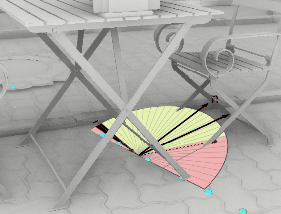
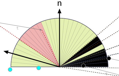
The following figure shows that the red sample front-face (leftmost dotted red line) is shifted according to the thickness vector t to create a backface (rightmost dotted red line):
With visibility bitmasks the UpdateHorizon() function from GTAO is not needed anymore, because we don’t need to apply any falloff! The constant thickness and the bitmask is enough to reproduce the attenuation over the distance in a plausible manner. It’s similar to ray tracing AO that doesn’t need any falloff heuristic either.
The UpdateSectors() function takes as input minHorizon and maxHorizon which represents the position of a sample in the hemisphere with a value between 0 and 1.
#define SECTOR_COUNT 32

uint UpdateSectors(float minHorizon, float maxHorizon, uint globalOccludedBitfield)
{
    uint startHorizonInt = minHorizon * SECTOR_COUNT;
    uint angleHorizonInt = ceil((maxHorizon-minHorizon) * SECTOR_COUNT);
    uint angleHorizonBitfield = angleHorizonInt > 0 ? (0xFFFFFFFF >> (SECTOR_COUNT-angleHorizonInt)) : 0;
    uint currentOccludedBitfield = angleHorizonBitfield << startHorizonInt;
    return globalOccludedBitfield | currentOccludedBitfield;
}
Sectors get activated from minHorizon to maxHorizon depending on the chosen rounding function:
- ceil: Sample needs to at least touch a sector to activate it
- round: Sample needs to cover at least half a sector to activate it
- floor: Sample needs to cover the entire sector to activate it
That pretty much covers the essential parts related to ambient occlusion using visibility bitmasks. It’s pretty simple to add into a horizon-based technique like GTAO, and it should make the occlusion better especially around thin surfaces with no noticeable impact on performance.